COMPONENTS
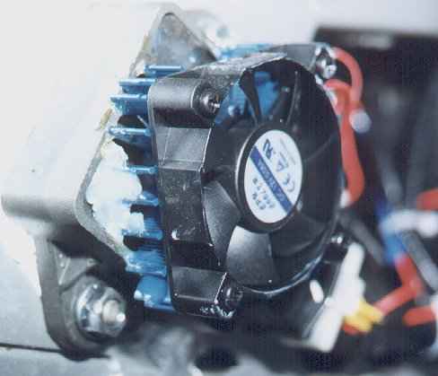
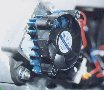
- Heat sink assembly. I decided to borrow one of the lists’suggestions and organised a Pentium PC heat sink and fan assembly (for Pentium 200)
-

- Heat transfer compound.
- Silicon rubber sealant.
PROCEDURE
- The bottom of the rectifier/regulator has a metal plate, which is used to transfer heat to the frame. I covered this with enough heat transfer compound to fill in the air gaps between the rectifier/regulator and the frame and bolted the unit back onto the frame.
-
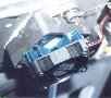
- The top of the rectifier/regulator is covered in silicon rubber to protect the components. I fixed the heat sink assembly to this with silicon rubber sealant. The heat sink / fan assembly is large enough to sit on the metal frame of the rectifier/regulator. Apply the silicon rubber sealant to the centre of the heat sink only, so as not to block the cooling fins around the rim of the heat sink. (A dab of epoxy resin can be applied to the corners of the heat sink assembly where it meets the rectifier/regulator for added adhesion).
-
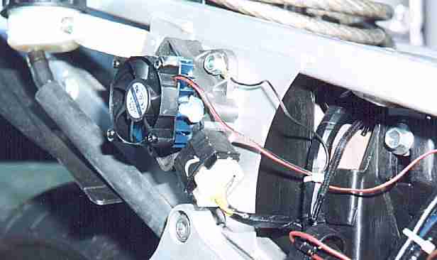
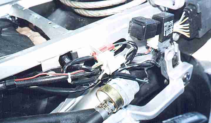
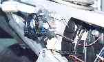
- Power to the heat sink fan was obtained from the brake light connector (in Australia, our headlights are wired to be on when the ignition is turned on. We don’t get a choice). Power for the fan can be taken from any number of points that are switched by the ignition, as the fan only draws .08 amps. The earth was taken from the bolt which fastens the rectifier/regulator to the frame.
-

* The heat sink assembly is only 1 inch high and allows ample clearance to the rear cowling
GOOD LUCK !